Not too long ago, I took the plunge into the world of Linux. Only to find myself constantly requiring to skip down to the command line to perform even some of the simplest of tasks. So when I learned about KontrollerLab, I was itching to get creative with it, and the "Digital Thermometer Project" is born.
Well to be quite honest, building a digital thermometer is a no-brainer. But I really had to do some building, or die of dull boredom.
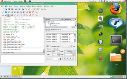
Those of us familiar with Unix/Linux (and other Posix based OSes) would understand why I felt frustrated when I had to keep getting down to the command line to do a simple $avr-gcc -mmcu=atxxxx -O0 -c /Projects/xxxxx/xxx.c. I wrote a few scripts to automate a few tasks, but that wasn't sufficient. When I learned of KontrollerLab IDE I wasn't too hopeful, I tried it not expecting much. Frankly, I was blown out of my mind. It was excellent! It is comparable to almost any good commercial Microcontroller Development IDE. Since it works with avr-gcc, it would be compatable with most of your existing code for the AVR.
Though it may seem that way, but this post is not about the development tool I have been emphasizing about so far! So lets discuss what we this post is really about. This weekend I'm building a Digital Thermometer.
Here is what we need.
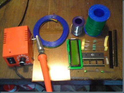
* Soldering Iron - Check.
* Random Wiring - Check.
* Some Discreets (Resistors, LED's etc.) - Check
* Headers and Sockets - Check.
* Microcontroller (ATMega32) - Check.
* LCD - Check.
* LM35 - Check.
* Geeky Brain - Check. ;)
OK, Good to go :D.
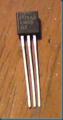
Now, Some may be wondering why I preferred the National Semiconductor LM35 over the much easier to use Dallas DS18x20. Well, for starters, I have a huge load of LM35's lying with me (remnants of an old project :P), and the second reason is, the LM35 is analogue, and pre-calibrated (yes, so is the DS18x, I know). And lastly since the LM35 is linear (10.0 mV/°C) it makes for easy calculation of the temperature from the sensor voltage. The sensor voltage is sampled using the ADC of the ATMega32. I wrote a C function to sample the ADC, it goes like:
void readAdcValue(int channel)
{
        ADMUX=channel|0x40;
        ADCSRA|=0x40;
        while ((ADCSRA & 0x10)==0);
        ADCSRA|=0x10;
        adcVal = ADCW;
}
For those not in the know, basically the function is using the ADMUX register to select the ADC channel that we are using, then we trigger the ADC Conversion using the ADSC (ADC Start Conversion) bit (bit 6) of the ADC Control and Status register (ADCSRA, we OR it with 0x40 i.e 0b 0100 0000). We then wait for the ADIF (ADC Interrupt Flag) to get set, then we sample the ADC value using the ADCW (ADC Word). ADCW is *not* a register. It is basically a combination of the ADCH and ADCL register. Remember the ATMega32 is an 8-bit processor, so all registers are 8-bit, and since the ADC is 10-bit, the ADCH (ADC High Value) and ADCL (ADC Low Value) registers are used.
Ok, Now we have an ADC reading, we have to convert that into a Sensor Voltage value and then convert that into a temperature.
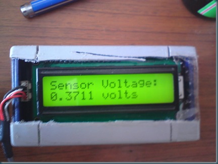
void showSensorVoltage(void)
{
	char* buff;
	lcd_gotoxy(0,0);
	lcd_puts("Sensor Voltage:");
	sensorVoltage = (adcVal * 1024)/5;
	buff = intToString(sensorVoltage);
	lcd_gotoxy(0,1);
	lcd_puts(buff);
}

void showSensorTemp(void)
{
	char* buff;
	lcd_gotoxy(0,0);
	lcd_puts("Temperature:");
	sensorTemp = (sensorVoltage * 500)/1024;
	buff = intToString(sensorTemp);
	lcd_gotoxy(0,1);
	lcd_puts(buff);
}
I use the equation,
sensorVoltage = (adcVal * 1024)/5;
and,
sensorTemp = (sensorVoltage * 500)/1024;
Ok, the code is divided into the following functions:
void init(void);
void showWelcome(void);
void showAdcValue(void);
void showSensorVoltage(void);
void showSensorTemp(void);
void readAdcValue(int);
char* intToString(int);
int main(void);
You can get a more detailed Idea by looking at the attached code.
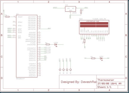
Ok, Time for the hardware assembly. I designed a schematic for the whole system:
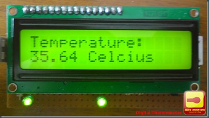
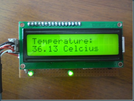
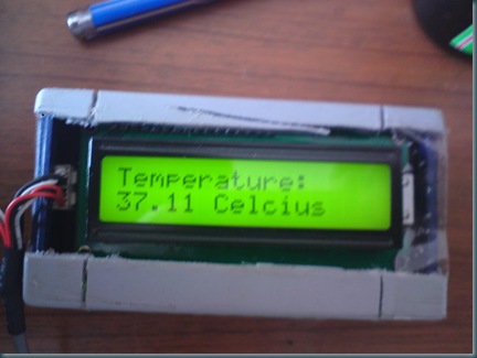
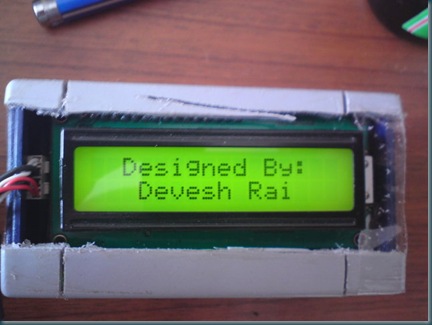
After hours of assembly and debugging:
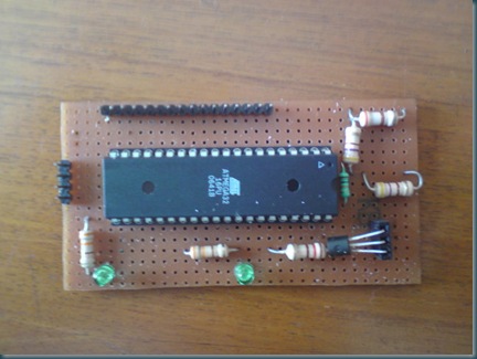
And it works!!!
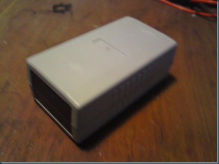
Case Modding:
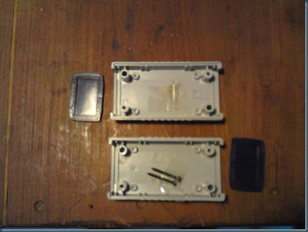
Ok, so now I need to make a case for this thing. I got a standard SMPS casing (again, leftovers from an older project) lying around.
The size is more or less right, but the insides are a bit messy
Anyhow, after some work, I managed to fit it all.... Not too neat. But not unacceptable either.
Thats all folks!!
Stay Tuned! :)


 ).
). , but I’d rather pen my idea down. I propose building a robot, which uses a very small form factor brain, does many (all?) of my common household tasks like fetch the soda, vacuum the room, feed the cat, wake me up from my slumber, play my music, water my ferns and kill the ladybugs in my 7th floor apartment (damned bugs!).


 )
)


