PART-2 : The TicTacToe Robot Controller

Now, that we have an algorithm working, what's next? Good question. Lets take a look again at the block diagram of our electronics:

Roughly based on the above I whipped together a Schematic:

Basically a Atmel (AVR) ATMega32, with a 2x16 Character LCD, a Keypad Matrix, and A set of headers for interfacing with the motion driving circuitry and sensors.
Step 1: Preparing the firmware.
This was main part, apparently porting the windows 'C#' code to plain 'C' wasn't all that simple, after all. Well it would have been , except:

So, I did a bit of optimization, and then some more, and then a LOT more. A poem would explain better:
"Till I had reduced each int to byte,
and byte to bit,
Till each hardware register was consumed,
Till each register could be used,
or Re-Used no more,
and Lo... I present to you the 'Optimized Code-Size'" 

This I'm particularly proud of. 
Anyway, the code is divided into 5 Files:
- main.c
- game.h
- game.c
- UserInterface.h
- UserInterface.c

Step 2: Preparing the hardware.
After getting the code "Out of the way", it was time to do what I really wanted to do this weekend. Time to get some Solder Iron Burns and some spit, wire and breadboards, together!!
Lets See what we need first. Hmmm....

-Solder Iron. Check.
-Bread Board. Check.
-LCD. Check.
-Microcontroller. Check
r step -Random Headers and Stuff. Check.
-Some Discreets. Check.
-Lots-a-Buttons. Check.
All clear. Lets go....
One Hour Later:

Everything assembled to my satisfaction, and ready for testing. 

It Works!!! It Works!!!
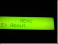
Some random screens:


Scrolling Up and Down the Menu:


Preparing the Outer Box: (I wish I had taken my art and crafts class in High school seriously 

Ooohhh the guts and wires.....
The Front Panel: (Before I got creative with a felt pen  )
)
 AAaahhh Finished....


Still Works....

Under the hood: Easy Access to the Microcontroller, and I/O Headers. I know, I'm a genius. 
 So, Thats it for now. What about the rest of the bot? Well the main part is over, I mean, the Code works on the Mega32, is now optimized, quite a bit, and I spent an entire long weekend (Long Weekend = Friday + Saturday + Sunday) on it, so it may be atleast another 3-4 weekends that this project will be on hold, so that I can work on other interesting projects. Nothing to be sad about... Next week, I'm working on Panasonic Servo based gantry (Ball Screw), with a Xilinx Spartan XC3S400. Nice....
If you like this post, leave a message, it always makes my day.


4 comments:
Nothing to do with your post... Actually was wondering why you'd have "Rita Pad" in your links. Do you own one of these printing machines?
I'm associated with that company.
Regards,
Debu :)
Superb!!!!
I absolutely love this idea of a tic tac toe bot...
:)
Post a Comment