Not too long ago, during a game of Monopoly, I thought to myself; "How the hell do I always end up loosing? I bet these dice are loaded!", and right then the geeky idea of building my own digital dice was born.
Idea
The Idea was to build a dice that:
- Produced 100% random result
- Easy to use, Simple button press and ... result
- Small enough to carry around with a board game
- Low power consumption, should run on battery power for long
- Ensure that every one knows that you are a geek ;)
Construction
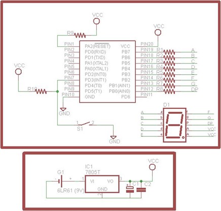 The hardware is based on an ATTiny 2313 processor, the main features of the hardware:
- Processor: AVR, ATTiny 2313.
- 7-Segment LED display (common anode) to display the digits.
- Thumb Switch to take input from the user
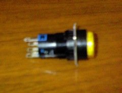
Thumb Switch - Battery as source of power.
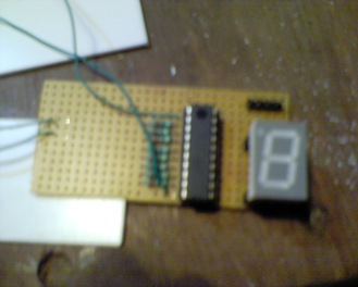
So, first I designed the hardware as per the schematics above onto a simple breadboard.
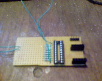
No Problem, simple circuit. I used headers to connect the 7-Segment LED display, this way, I could remove the display as and when required.
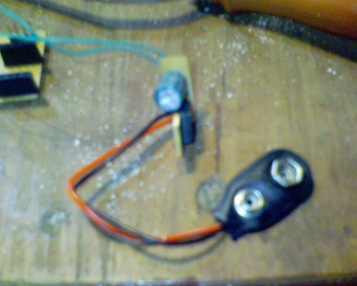
Ok, That's done! Now to work on the battery and regulator circuit. Here I decided to use a LM7805 regulator, along with a 1000uF and a 100uF capacitor, to deal with the casual drop in voltage when the circuit starts drawing current. I used common 9V 6LR61 batteries to power the regulator.
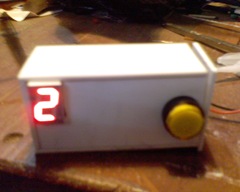
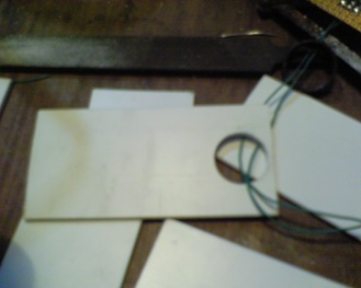
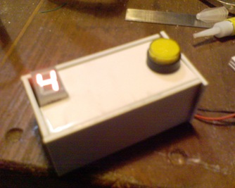
For the casing, I got some thin and light ABS Plastic pieces from my throw away waste.

I cut and filed them to a somewhat desirable size.
Drilled a nice hole for thumb switch.
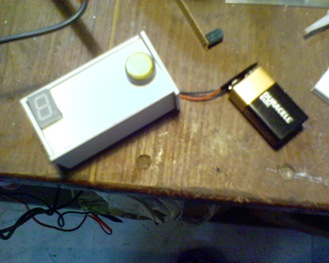
And.....Done!
Software
I wrote the code for the processor in assembly, what I am showing here is only the skeleton structure. The complete code is available in the download package.
First is the Reset Vector ,GetButtonPress and the ButtonPressed routines:
1: .include "tn2313def.inc"
2:
3: .org 0x0000
4: RJMP Reset //Code Starts from Address 0x0000
5:
6: Reset: //Reset Vector
7: RJMP Init
8: RJMP GetButtonPress
9: RJMP Reset
10:
11: GetButtonPress:
12: SBIC PORTD, 3 //Skip if Bit is Clear on PD3
13: RJMP GetButtonPress //Relative Jump to Label
14: RJMP ButtonPressed //Relative Jump to Label
15: RJMP GetButtonPress
16:
17: ButtonPressed:
18: SBIC PORTD, 3 //Skip if Bit is Set on PD3
19: RJMP ShowResult //Relative Jump to ShowResult
20: INC R17 //Increment Register R17
21: INC R16 //Increment Register R16
22: CPI R17, 0xFF //Compare Immediate R17 and 0xFF
23: BREQ ToggleDP //Branch if Equal to ToggleDP
24: LDI R18, 0x06 //Load R18 with with Immediate 0x06
25: CPSE R18, R16 //Compare, Skip if Equal
26: RJMP ButtonPressed//Relative Jump to ButtonPressed
27: CLR R16 //Clear Register R16
28: RJMP ButtonPressed
The skeleton routine above does not take into account the debounce of the thumb switch. The thumb switch being used is spring loaded, and has a magnetic catch inside it, so the typical debounce would be around ~80ms. Now, running at 8MIPS (internal RC oscillator), in terms of processor cycles, that would be; 1 sec = 8,000,000 instructions; 1ms = 8,000 instructions; 80ms = 64,000 instructions; That means we need to call nop 64,000 times to debounce the switch correctly.
Next we have the ShowResult routine. This basically displays on our 7-Segment display the value of the roll.
1: ShowResult:
2: LDI R18, 0x01 //Load Immediate R18, with 0x01
3: CP R16, R18 //Compare R16 and R18
4: BREQ ShowOne//Branch if Equal to ShowOne
5: LDI R18, 0x02 //Load Immediate R18, with 0x02
6: CP R16, R18 //Compare R16 and R18
7: BREQ ShowTwo//Branch if Equal to ShowOne
8: LDI R18, 0x03 //Load Immediate R18, with 0x03
9: CP R16, R18 //Compare R16 and R18
10: BREQ ShowThr//Branch if Equal to ShowOne
11: LDI R18, 0x04 //Load Immediate R18, with 0x04
12: CP R16, R18 //Compare R16 and R18
13: BREQ ShowFou//Branch if Equal to ShowOne
14: LDI R18, 0x05 //Load Immediate R18, with 0x05
15: CP R16, R18 //Compare R16 and R18
16: BREQ ShowFiv//Branch if Equal to ShowOne
17: LDI R18, 0x06 //Load Immediate R18, with 0x06
18: CP R16, R18 //Compare R16 and R18
19: BREQ ShowSix//Branch if Equal to ShowSix
20: RJMP ShowResult
One more important consideration here is Low Power Mode, and automatic turn off (We are running on batteries here, after all). In the final code, I have included a low power and auto turn of routine. This checks to see if the dice is not used for 4 Seconds or more, and then turns off the display and puts the processor and other peripherals in a low power state. See the video of operation below to get a good idea of how this works.
Ok, thats it!! All Done now!!
And it Works!! :D
Video of Operation:
Thats all folks, Untill Next Time!! If you like this entry, Leave a message and Digg this article. Messages always make my day. :)


