Saturday, July 18, 2009

Classic Snake Game


Another simple weekend project, the Classic Snake Game. This one should serve as an example for anyone who wants to learn the anatomy of a snake game (or its clones: Nibbles, Worms etc.). The code is open source and available under GNU GPLv3 for use and reuse. Both, the code and the binaries are available for download at the projects Google Code repository. Be sure to leave your view and comments, they always make my day.

Thursday, April 23, 2009

n00b Translator

Screenshot-2 

A simple fun project, which translates L337 to n00b readable English. Open source project, the code is available in the project's Google Code Website. This can serve as a great example for Java text processing.


Stay tuned. :D

Thursday, January 1, 2009

Digital Dice Using ATTiny 2313

DSC00016

Not too long ago, during a game of Monopoly, I thought to myself; "How the hell do I always end up loosing? I bet these dice are loaded!", and right then the geeky idea of building my own digital dice was born.

Idea
The Idea was to build a dice that:

  • Produced 100% random result
  • Easy to use, Simple button press and ... result
  • Small enough to carry around with a board game
  • Low power consumption, should run on battery power for long
  • Ensure that every one knows that you are a geek ;)

Construction
schematic The hardware is based on an ATTiny 2313 processor, the main features of the hardware:

  • Processor: AVR, ATTiny 2313.
  • 7-Segment LED display (common anode) to display the digits.
  • Thumb Switch to take input from the user
    DSC00018 
    Thumb Switch
  • Battery as source of power.

So, first I designed the hardware as per the schematics above onto a simple breadboard.
DSC00011

No Problem, simple circuit. I used headers to connect the 7-Segment LED display, this way, I could remove the display as and when required.
DSC00008 
Ok, That's done! Now to work on the battery and regulator circuit. Here I decided to use a LM7805 regulator, along with a 1000uF and a 100uF capacitor, to deal with the casual drop in voltage when the circuit starts drawing current. I used common 9V 6LR61 batteries to power the regulator.
DSC00012
For the casing, I got some thin and light ABS Plastic pieces from my throw away waste.
DSC00006 
I cut and filed them to a somewhat desirable size.
DSC00007
Drilled a nice hole for thumb switch.
DSC00013
And.....Done!

Software
I wrote the code for the processor in assembly, what I am showing here is only the skeleton structure. The complete code is available in the download package.

First is the Reset Vector ,GetButtonPress and the ButtonPressed routines:

   1: .include "tn2313def.inc"
   2:  
   3: .org 0x0000
   4:     RJMP Reset    //Code Starts from Address 0x0000
   5:  
   6: Reset:            //Reset Vector
   7:     RJMP Init
   8:     RJMP GetButtonPress
   9: RJMP Reset
  10:  
  11: GetButtonPress:
  12:     SBIC PORTD, 3        //Skip if Bit is Clear on PD3
  13:     RJMP GetButtonPress    //Relative Jump to Label
  14:     RJMP ButtonPressed    //Relative Jump to Label
  15: RJMP GetButtonPress
  16:  
  17: ButtonPressed:
  18:     SBIC PORTD, 3      //Skip if Bit is Set on PD3
  19:     RJMP ShowResult      //Relative Jump to ShowResult
  20:     INC    R17                //Increment Register R17
  21:     INC    R16                //Increment Register R16
  22:     CPI    R17, 0xFF       //Compare Immediate R17 and 0xFF
  23:         BREQ ToggleDP //Branch if Equal to ToggleDP
  24:     LDI R18, 0x06     //Load R18 with with Immediate 0x06
  25:     CPSE R18, R16      //Compare, Skip if Equal
  26:     RJMP ButtonPressed//Relative Jump to ButtonPressed
  27:     CLR    R16              //Clear Register R16
  28: RJMP ButtonPressed

The skeleton routine above does not take into account the debounce of the thumb switch. The thumb switch being used is spring loaded, and has a magnetic catch inside it, so the typical debounce would be around ~80ms. Now, running at 8MIPS (internal RC oscillator), in terms of processor cycles, that would be;  1 sec = 8,000,000 instructions; 1ms = 8,000 instructions; 80ms = 64,000 instructions; That means we need to call nop 64,000 times to debounce the switch correctly.


Next we have the ShowResult routine. This basically displays on our 7-Segment display the value of the roll.


   1: ShowResult:
   2:     LDI    R18, 0x01    //Load Immediate R18, with 0x01
   3:     CP    R16, R18    //Compare R16 and R18
   4:         BREQ ShowOne//Branch if Equal to ShowOne
   5:     LDI    R18, 0x02    //Load Immediate R18, with 0x02
   6:     CP    R16, R18    //Compare R16 and R18
   7:         BREQ ShowTwo//Branch if Equal to ShowOne
   8:     LDI    R18, 0x03    //Load Immediate R18, with 0x03
   9:     CP    R16, R18    //Compare R16 and R18
  10:         BREQ ShowThr//Branch if Equal to ShowOne
  11:     LDI    R18, 0x04    //Load Immediate R18, with 0x04
  12:     CP    R16, R18    //Compare R16 and R18
  13:         BREQ ShowFou//Branch if Equal to ShowOne
  14:     LDI    R18, 0x05    //Load Immediate R18, with 0x05
  15:     CP    R16, R18    //Compare R16 and R18
  16:         BREQ ShowFiv//Branch if Equal to ShowOne
  17:     LDI    R18, 0x06    //Load Immediate R18, with 0x06
  18:     CP    R16, R18    //Compare R16 and R18
  19:         BREQ ShowSix//Branch if Equal to ShowSix
  20: RJMP ShowResult

One more important consideration here is Low Power Mode, and automatic turn off (We are running on batteries here, after all). In the final code, I have included a low power and auto turn of routine. This checks to see if the dice is not used for 4 Seconds or more, and then turns off the display and puts the processor and other peripherals in a low power state. See the video of operation below to get a good idea of how this works.


Ok, thats it!! All Done now!!
DSC00015 
And it Works!! :D


Video of Operation:


Thats all folks, Untill Next Time!! If you like this entry, Leave a message and Digg this article. Messages always make my day. :)

Sunday, November 9, 2008

The heights of geekiness

Geek noun \ˈgēk\: Geek  Used in a nice way it is someone who seems to know everything there is to know about computers.

If I were to define myself as a geek, I would say:

   1:    -----BEGIN GEEK CODE BLOCK-----
   2:    Version: 3.12
   3:    GED/J d-- s:++>: a-- C+++(++++) 
   4:    ULU++ P+ L++ E---- W+(-) N+++ 
   5:    o+ K+++ w---  O- M+ V-- PS++>
   6:    $ PE++>$ Y++ PGP++ t- 5+++ 
   7:    X++ R+++>$ tv+ b+ DI+++ D+++
   8:    G+++++ e++ h r-- y++**
   9:    ------END GEEK CODE BLOCK------


(don't understand the above? refer to The Geek Code v3.12, Yup, we have one) smile_nerd


Even as a geek, there comes a point, where you need to draw the line. One such point came today. I found myself facing a dilemma, unable to decide, "How to get bored today". After much deliberation I found that I simply could not decide between five things to do. Under these circumstances I decided a coin toss would be ideal. This of course brought up another question how best to decide between 5 choices using a coin. At that time a brilliant geeky idea came to me, and I decided to whip together a "Random Choice Maker"


Screenshot


Took me 20 minutes to whip together this simple utility, I wrote a simple RNG function it went like:


   1: class myRandomizerClass
   2: {
   3:     public int generateRandomValue(int uValue)
   4:     {
   5:         int millisecondsNow = DateTime.Now.Millisecond, breakIndex = 1000/uValue;
   6:         return millisecondsNow/breakIndex;
   7:     }
   8: }


It uses a simple uValue for checking quantile density.


So, that's it. Once again I ended up prooving that "Once a geek, always a Geek"


Cheerio. smile_tongue

Sunday, September 28, 2008

Digital Thermometer


Thermometer

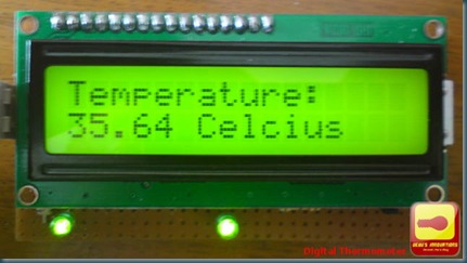
Not too long ago, I took the plunge into the world of Linux. Only to find myself constantly requiring to skip down to the command line to perform even some of the simplest of tasks. So when I learned about KontrollerLab, I was itching to get creative with it, and the "Digital Thermometer Project" is born.

Well to be quite honest, building a digital thermometer is a no-brainer. But I really had to do some building, or die of dull boredom.

Those of us familiar with Unix/Linux (and other Posix based OSes) would understand why I felt frustrated when I had to keep getting down to the command line to do a simple $avr-gcc -mmcu=atxxxx -O0 -c /Projects/xxxxx/xxx.c. I wrote a few scripts to automate a few tasks, but that wasn't sufficient. When I learned of KontrollerLab IDE I wasn't too hopeful, I tried it not expecting much. Frankly, I was blown out of my mind. It was excellent! It is comparable to almost any good commercial Microcontroller Development IDE. Since it works with avr-gcc, it would be compatable with most of your existing code for the AVR.
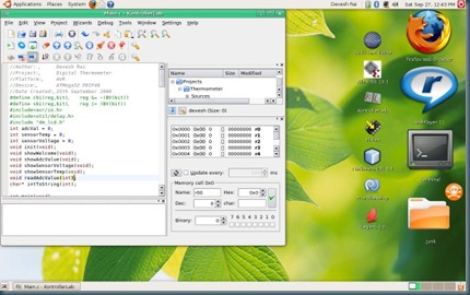
Screenshot

Though it may seem that way, but this post is not about the development tool I have been emphasizing about so far! So lets discuss what we this post is really about. This weekend I'm building a Digital Thermometer.

Here is what we need.
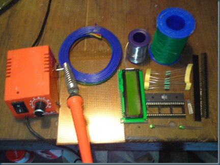
dsc00032

* Soldering Iron - Check.
* Random Wiring - Check.
* Some Discreets (Resistors, LED's etc.) - Check
* Headers and Sockets - Check.
* Microcontroller (ATMega32) - Check.
* LCD - Check.
* LM35 - Check.

* Geeky Brain - Check. ;)

OK, Good to go :D.
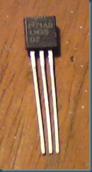
 LM35

Now, Some may be wondering why I preferred the National Semiconductor LM35 over the much easier to use Dallas DS18x20. Well, for starters, I have a huge load of LM35's lying with me (remnants of an old project :P), and the second reason is, the LM35 is analogue, and pre-calibrated (yes, so is the DS18x, I know). And lastly since the LM35 is linear (10.0 mV/°C) it makes for easy calculation of the temperature from the sensor voltage. The sensor voltage is sampled using the ADC of the ATMega32. I wrote a C function to sample the ADC, it goes like:

void readAdcValue(int channel)
{
ADMUX=channel|0x40;
ADCSRA|=0x40;
while ((ADCSRA & 0x10)==0);
ADCSRA|=0x10;
adcVal = ADCW;
}


For those not in the know, basically the function is using the ADMUX register to select the ADC channel that we are using, then we trigger the ADC Conversion using the ADSC (ADC Start Conversion) bit (bit 6) of the ADC Control and Status register (ADCSRA, we OR it with 0x40 i.e 0b 0100 0000). We then wait for the ADIF (ADC Interrupt Flag) to get set, then we sample the ADC value using the ADCW (ADC Word). ADCW is *not* a register. It is basically a combination of the ADCH and ADCL register. Remember the ATMega32 is an 8-bit processor, so all registers are 8-bit, and since the ADC is 10-bit, the ADCH (ADC High Value) and ADCL (ADC Low Value) registers are used.


Ok, Now we have an ADC reading, we have to convert that into a Sensor Voltage value and then convert that into a temperature.


void showSensorVoltage(void)
{
char* buff;
lcd_gotoxy(0,0);
lcd_puts("Sensor Voltage:");
sensorVoltage = (adcVal * 1024)/5;
buff = intToString(sensorVoltage);
lcd_gotoxy(0,1);
lcd_puts(buff);
}

void showSensorTemp(void)
{
char* buff;
lcd_gotoxy(0,0);
lcd_puts("Temperature:");
sensorTemp = (sensorVoltage * 500)/1024;
buff = intToString(sensorTemp);
lcd_gotoxy(0,1);
lcd_puts(buff);
}


I use the equation,

sensorVoltage = (adcVal * 1024)/5;


and,


sensorTemp = (sensorVoltage * 500)/1024;


Ok, the code is divided into the following functions:


void init(void);
void showWelcome(void);
void showAdcValue(void);
void showSensorVoltage(void);
void showSensorTemp(void);
void readAdcValue(int);
char* intToString(int);
int main(void);


You can get a more detailed Idea by looking at the attached code.


Ok, Time for the hardware assembly. I designed a schematic for the whole system:
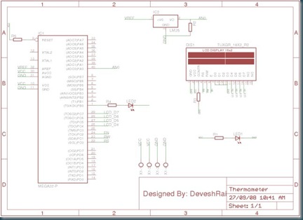


Schematic


After hours of assembly and debugging:
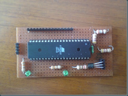


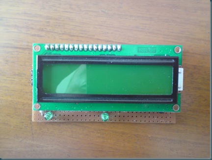
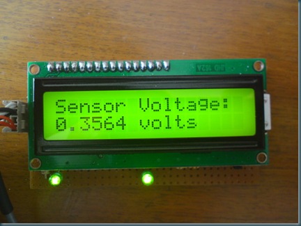
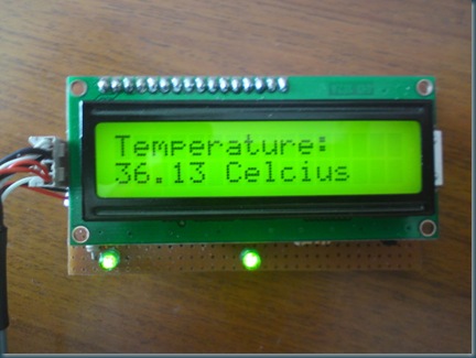
dsc00026


dsc00022


And it works!!!dsc00027


dsc00029


Case Modding:


Ok, so now I need to make a case for this thing. I got a standard SMPS casing (again, leftovers from an older project) lying around.
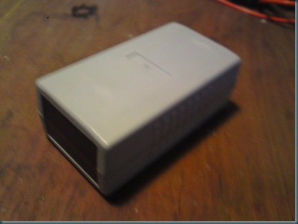


dsc00037


The size is more or less right, but the insides are a bit messy
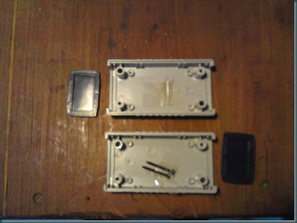


dsc00040


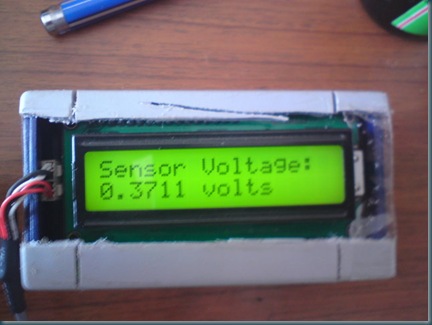
Anyhow, after some work, I managed to fit it all.... Not too neat. But not unacceptable either.
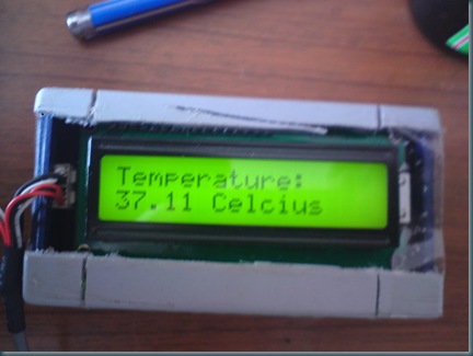

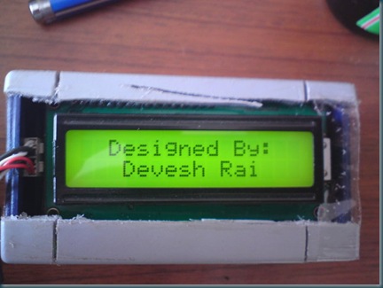
dsc00015  


dsc00017


dsc00020


Thats all folks!!


Stay Tuned! :)

Non-Geek: My Friends Blog


Well Guys long time since I posted anything around here, Its time to clean out the cobwebs and move in again. :)

To start out, my Friend, and Clan member the one and only Mr. Riteek "VoLdEmOrT" Arora is on Blogger now, I'm sure all the Geeks and even the Non-Geeks (do we get that kind around here? ;) ) would enjoy his blog. His interests involve around F1, Linux (apparently Harry Potter Characters ;) ), well....You read his blog.

DSC01153    
Pictured above: Mr. Riteek "VoLdEmOrT" Arora

Visit his blog: RiTeEk "VoLdEmOrT" aRoRa'S Blog


Cheerio!! PS. A geeky entry is coming soon....Stay tuned!

Sunday, April 20, 2008

TicTacToe Bot (Part 2)

PART-2 : The TicTacToe Robot Controller

IMG_0140

Now, that we have an algorithm working, what's next? Good question. Lets take a look again at the block diagram of our electronics:

 block-diagram

Roughly based on the above I whipped together a Schematic:

Schematic

Basically a Atmel (AVR) ATMega32, with a 2x16 Character LCD,  a Keypad Matrix,  and A set of headers for interfacing with the motion driving circuitry and sensors.

Step 1: Preparing the firmware.

This was main part, apparently porting the windows 'C#' code to plain 'C' wasn't all that simple, after all. Well it would have been , except:

Error_mem

So, I did a bit of optimization, and then some more, and then a LOT more. A poem would explain better:

"Till I had reduced each int to byte,

and byte to bit,

Till each hardware register was consumed,

Till each register could be used,

or Re-Used no more,

and Lo... I present to you the 'Optimized Code-Size'" smile_shades

new_mem

This I'm particularly proud of. clap

Anyway, the code is divided into 5 Files:

  • main.c
  • game.h
  • game.c
  • UserInterface.h
  • UserInterface.c

Program Structure

Step 2: Preparing the hardware.

After getting the code "Out of the way", it was time to do what I really wanted to do this weekend. Time to get some Solder Iron Burns and some spit, wire and breadboards, together!!

Lets See what we need first. Hmmm....

IMG_0120

-Solder Iron. Check.

-Bread Board. Check.

-LCD. Check.

-Microcontroller. Check

r step -Random Headers and Stuff. Check.

-Some Discreets. Check.

-Lots-a-Buttons. Check.

All clear. Lets go....thumbs_up

One Hour Later:

IMG_0121

Everything assembled to my satisfaction, and ready for testing. fingerscrossed

IMG_0122

It Works!!! It Works!!!

Some random screens:

IMG_0128

IMG_0130

Scrolling Up and Down the Menu:

IMG_0123

IMG_0124

IMG_0125

IMG_0126 IMG_0127

IMG_0131 IMG_0133 IMG_0134

Preparing the Outer Box: (I wish I had taken my art and crafts class in High school seriously smile_thinking

IMG_0135

Ooohhh the guts and wires.....IMG_0136

The Front Panel: (Before I got creative with a felt pen smile_wink)

IMG_0137  AAaahhh Finished.... clapthumbs_upbeer

IMG_0139


IMG_0140

Still Works....

IMG_0142

Under the hood: Easy Access to the Microcontroller, and I/O Headers. I know, I'm a genius. smile_teeth

IMG_0138  So, Thats it for now. What about the rest of the bot? Well the main part is over, I mean, the Code works on the Mega32, is now optimized, quite a bit, and I spent an entire long weekend (Long Weekend = Friday + Saturday + Sunday) on it, so it may be atleast another 3-4 weekends that this project will be on hold, so that I can work on other interesting projects. Nothing to be sad about... Next week, I'm working on Panasonic Servo based gantry (Ball Screw), with a Xilinx Spartan XC3S400. Nice....


If you like this post, leave a message, it always makes my day.smile_regular